What Is a Hydraulic Puller and Why Tonnage Selection Matters
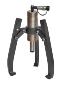
A hydraulic puller is a dedicated extraction tool. It uses pressurized hydraulic fluid to generate controlled pulling force. The goal is to remove press-fitted components — bearings, gears, couplings — from shafts.
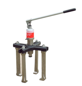
The mechanism is simple. A pump builds pressure inside the hydraulic cylinder. That pressure pushes a piston forward. The piston drives the center ram against the shaft end. At the same time, the jaws grip the component from behind. Both forces push against each other until the component breaks free.

What separates it from a mechanical screw puller isn’t just convenience. It’s physics.
Pascal’s Law explains it: pressure applied to a confined fluid spreads in all directions with no meaningful loss. At 700 bar — the standard operating pressure for most industrial hydraulic systems — a cylinder area of just 10 cm² produces 7 tons of pulling force. Scale that up, and a 50-ton puller needs around 71 cm² of effective piston area at the same pressure.
A mechanical puller works differently. It converts hand torque through a threaded screw. Realistic output: 2 to 5 tons. Thread friction and wear cut that number down fast.
Tonnage selection isn’t a minor detail. Pick too little, and the job stalls — or the component gets damaged. Get it right, and the job is done clean.
The 10:1 Rule: How to Calculate the Right Tonnage for Your Application

Here’s the formula every maintenance tech should write on their toolbox: shaft diameter (inches) × 10 = minimum tonnage.
That’s it. A 2-inch shaft needs a 20-ton puller. A 5-inch shaft needs a 50-ton puller. The math takes three seconds.
Field technicians have used this rule for decades as a fast starting point. Not because it’s perfect — but because it’s a reliable first step. It puts you in the right range before the real variables come into play.
The Variables That Change Everything
The 10:1 rule gives you a baseline. Four more factors shape the actual tonnage you need:
- Fit type. A clean slip fit stays close to the base estimate. An interference or press fit can demand 1.5× to 2× more force.
- Corrosion and seizure. Rust is a multiplier. Moderate oxidation adds 25–50% to the required force. Badly seized components can double or triple that. Budget 2× to 3× the base estimate for anything that’s been sitting.
- Engagement length. A longer hub contact surface builds more resistance. Shaft diameter alone won’t capture that.
- Material pairing. Steel-on-steel needs more force than softer hub materials. Aluminum hubs may deform before they let go.
Correction Factors in Practice
Take a 2-inch shaft. Base estimate: 20 tons.
| Condition | Adjusted Tonnage |
|---|---|
| Clean / slip fit | 20 ton |
| Interference fit | 30–40 ton |
| Rusted / seized | 40–60 ton |
One more rule: if your calculation lands near the top of a tool class, move up. A calculated 38-ton requirement means you buy a 50-ton hydraulic puller. That extra margin covers fit variation, thread friction, and real-world binding. These things never show up in the formula. They always show up on the job.
Quick Reference by Shaft Size
| Shaft Diameter | Base Tonnage |
|---|---|
| 1 in | 10 ton |
| 2 in | 20 ton |
| 3 in | 30 ton |
| 4 in | 40 ton |
| 5 in | 50 ton |
| 6 in | 60 ton |
Start with this table. Add your correction factors. Then round up to the next tool class if you’re anywhere close to the ceiling.
Choosing a 5-Ton Hydraulic Puller
The 5-ton hydraulic puller has a clear lane. Stay in it, and the tool performs. Stray outside it, and you’ll be grabbing something bigger mid-job.
The boundary is shaft diameter. At or below 0.5″ (12–13 mm), a 5-ton unit fits the application. Use the 10:1 rule: a 0.5″ shaft needs 5 tons — no more, no less. Clean fit, light corrosion, indoor environment — that’s where this tool earns its place.

Where It Works
- Small electric motor bearings — fractional-horsepower motors (0.25–1 hp) run 8–12 mm shafts. This tool fits them well.
- Automotive pulleys and idlers — alternator pulleys, tensioner pulleys, and small belt idlers on passenger cars and light trucks are all solid matches.
- Light machinery components — small sprockets, couplings, and sleeves on packaging machines, printers, and compact pumps with 10–12 mm shafts. Straightforward jobs for this tool.
- Tight-access jobs — the compact frame and 4–8 kg weight slide into cramped housings. A 50-ton unit won’t fit there.
Where It Breaks Down
Shaft diameter is just the first filter. Two conditions push you past 5 tons even on a small shaft:
Severe corrosion. Visible rust, pitting, or years of wet-environment service can shoot required force well past what the diameter math suggests. Move to a 10-ton in that case.
High interference fits. Shrink-fitted components or heavy press fits on even a 0.5″ shaft can demand more than 5 tons. Don’t know how the part was assembled — heat, cold, lubrication? Don’t bet on the smaller tool.
The Operating Rule
Run a 5-ton hydraulic puller at 50–70% of rated capacity during normal pulls. Your estimated required force is already pushing 4 tons? Buy the 10-ton. That extra headroom keeps the tool intact and the job moving.
| Shaft Diameter | Condition | Verdict |
|---|---|---|
| ≤ 0.5″ (12–13 mm) | Clean, normal fit | 5-ton: good match |
| 0.5–0.75″ | Moderate conditions | 10-ton: safer choice |
| > 0.75″ | Any | 10-ton minimum |
The 5-ton is a precision instrument for small, light, accessible work. It’s not a compromise — it’s the right tool for a specific job. Know the job first.
Choosing a 50-Ton Hydraulic Puller
The 50-ton hydraulic puller doesn’t belong in small motor shops. It lives in steel mills, mine shafts, and wind farms — places where a 20-ton tool simply can’t do the job.
Shaft diameter is the clearest signal. Cross 90 mm, and extraction forces land in the 30–50 ton range. Push past 130 mm, and 50-ton becomes your starting point, not your limit.
The Applications That Demand It
Heavy industrial drives. Rolling mills, mixers, and cement kiln drives run 120–300 mm mainshafts. Gear and coupling removal on those shafts needs 40–80 tons of pulling force. That’s before corrosion even enters the picture.
Large motors and generators. Motors above 500 kW seat their bearings and couplings under extreme load. Generator rotors with diameters over 600 mm do the same. A 20-ton puller won’t move them. Long service hours build up fretting and pressure marks that bond the inner race tight to the shaft.
Mining equipment. Primary crusher mainshafts at ≥150 mm diameter, drive pulleys wider than 1 meter — these are standard maintenance targets in mining, not rare exceptions. The 50-ton setup is what field crews bring in by default.
Marine propulsion shafts. Shaft diameters ≥150 mm combined with seawater pitting push actual extraction force far beyond what any interference calculation predicts. Saltwater corrosion multiplies the load fast. Undersized tools don’t survive it.
The Hard Upgrade Triggers
Go straight from 20-ton to 50-ton if any of these apply:
- Fit class is H7/p6 or tighter, with long-term operating temperatures above 80°C
- Shaft diameter falls between 90–130 mm with visible corrosion or seizure
- The component was assembled with heat shrinking and you can’t pre-heat it during removal
One more thing: a 50-ton hydraulic puller isn’t just a bigger version of what you already have. The Cylinder walls, jaw cross-sections, and frame are built to a different standard — 42CrMo forged steel, induction-hardened jaw faces, seals rated to 63 MPa. That extra structural margin is what keeps the tool in one piece when real-world conditions blow past the spec sheet.
Choosing a 100-Ton Hydraulic Puller
Some jobs don’t ask permission. The shaft is 400 mm across. It’s been interference-fitted under heat for a decade. It isn’t moving — not with a 50-ton puller, not with persuasion, not with anything short of real force.
That’s where the 100-ton hydraulic puller earns its place.
The trigger is clear. Your estimated extraction force hits 70 tons or above — factoring in interference fit, corrosion, and engagement length. A 50-ton unit is already near its rated limit. You move up. The margin you need is at least 30%. Anything less, and you’re not doing maintenance. You’re running an experiment.
The Applications That Require It
Rolling mills. Hot and cold mill rolls run 400–800 mm in diameter. Bearing outer races hit 300–600 mm. Long-term high-temperature interference fits on those components beat 50-ton equipment — consistently. Field crews bring 80–100-ton units as standard, not as backup.
Heavy press machinery. Crankshaft diameters run 300–500 mm. Flywheels weigh 1–5 tons. Eccentric wheels carry deep interference fits. Pulling them free — without hammer damage to the frame — takes 70+ tons of controlled, coaxial force.
Port craneage. Crane wheels ≥600 mm, drum shafts with taper-and-key connections, slewing ring races. Port maintenance specs list the 100-ton puller as the default tool for wheel set removal — not a special order.
Offshore wind turbines. Main bearing outer diameters on 3–8 MW turbines reach 1–2 meters. A single bearing can weigh up to 7 tons. Inside a nacelle, clearance is tight. There’s no space for a hollow cylinder-and-rod arrangement. The 100-ton puller is self-centering and compact for its capacity. It fits the space and gets the job done.
What Changes at This Scale
This isn’t a larger version of your 50-ton setup. The hydraulic system runs at 700 bar through hoses and fittings built to a 4:1 safety factor minimum — burst pressure above 2,800 bar. To reach 100 tons at 700 bar, the piston needs to be 134 mm in diameter. That diameter drives wall thickness, jaw cross-section, and frame design across the entire unit.
At this capacity, hand pumps don’t cut it. You pair the puller with an electric or pneumatic pump station. High-pressure flow of 0.5–3 L/min keeps the pull steady — without wearing out the operator over hundreds of pump strokes.
One rule has no exceptions: no one stands in line with the pull axis at forces above 50 tons. At 100 tons, a failure isn’t loud — it’s catastrophic. Use remote foot-pedal or electronic valve control to keep personnel clear of the pull axis at all times.
2-Jaw vs 3-Jaw: Which Configuration Fits Your Job
Tonnage gets you to the job. Jaw configuration determines whether you finish it.
The geometry is simple, and it matters. A 2-jaw hydraulic puller splits the load between two contact points, 180° apart. A 3-jaw splits it across three points at 120° intervals. That 60-degree difference changes everything — load per jaw, centering behavior, slip risk, and what happens to precision-fitted components when the pull releases.
When 2-Jaw Wins
Space is the deciding factor. The third jaw can’t always reach. A shaft shoulder up against a housing wall, a coupling flush against a bearing seat rib — in those cases, a 2-jaw puller is your only option. Some 2-jaw designs work inside a 60–70° arc of clearance. A 3-jaw needs at least 120°.
Irregular geometry is the second reason. A gear with a keyway on one side. A pulley with a casting rib. A bearing outer race with two clean Flanges and nothing between them. These are 2-jaw situations. Put a three-point grip on an asymmetric workpiece and one jaw lands on air. It will slip.
Practical example: Removing an 80 mm pulley seated tight against a motor housing. The 3-jaw needs 90–100 mm of continuous Flange around the full circumference. The 2-jaw needs just ≥20 mm of clean bearing surface on opposite sides. That’s often all you get.
Running 2-jaw? Compensate for the load concentration:
Use a crosswise strap or wire rope to keep both jaws from spreading under load
Choose jaw tips with deeper tooth profiles — 1–2 mm depth, 60°–90° tip angle — for grip retention
Add load in steps of 5–10% at a time. Check jaw seating after each step
Size up one tonnage class. A job that calls for a 20-ton 3-jaw setup needs a 30-ton 2-jaw to hold the same safety margin at the jaw root
When 3-Jaw Is the Right Call
Three-point contact doesn’t just spread the load — it cancels lateral bending moment. Two jaws create a bending moment any time the puller axis is off-center from the component. Three jaws, loaded evenly, cancel those moments out. The workpiece gets clean axial force and nothing else.
At 30 tons total pull:
– 2-jaw: each jaw carries ≈15 tons
– 3-jaw: each jaw carries ≈10 tons — a 33% drop in per-jaw stress
That stress difference shows up in the material. Jaw root stress on a 2-jaw runs 1.5× higher than on a 3-jaw at the same rated capacity. Above 20–30 tons, that gap forces a choice: oversized jaw arms that won’t fit in tight spaces, or more expensive alloy and heat treatment.
For precision components, the 3-jaw case is even stronger. H7/p6 interference fits, P5 and P4 grade bearings, encoder wheels, machine tool spindle gears — these are parts where a tilted pull leaves damage. Field data from tooling manufacturers shows shaft journal scoring risk drops 30–50% with a centered 3-jaw pull compared to a 2-jaw pull on the same fit class.
Thin copper or aluminum shims (0.5–1 mm) between the jaw tips and workpiece surface add even more protection. Three contact points hold those shims steady. Two don’t.
Above 30 tons, go with 3-jaw. At 50 or 100 tons, a 2-jaw slip isn’t just a problem — it’s a projectile event. Three jaws mean one contact can shift and two still hold. That backup is exactly why large-bore bearing and coupling jobs specify 3-jaw Hydraulic Pullers as standard, not optional.
The Decision in One Table
| Condition | 2-Jaw | 3-Jaw |
|---|---|---|
| Restricted radial clearance (<120°) | ✓ | — |
| Asymmetric workpiece (keyway, rib, cutout) | ✓ | — |
| Symmetric, full-perimeter flange | — | ✓ |
| Precision fit (H7/p6 or tighter) | — | ✓ |
| Pull force >30 ton | — | ✓ |
| Slender shaft (L/D >6) | — | ✓ |
Jaw count isn’t a preference. It’s a function of the geometry in front of you and the force needed to move it.
5 Hydraulic System Quality Indicators You Cannot Ignore
The hydraulic system is where most cheap pullers fail. Not on the first job. On the fifteenth.
By then, you’ve already trusted the tool. That’s the problem.
Five indicators separate a hydraulic puller that holds up under real industrial loads from one that becomes a liability. Each one is measurable. None of them show up on the product listing.
1. Overpressure Protection: Relief Valve Setting
The relief valve isn’t a feature. It’s the difference between a controlled pull and a high-pressure injection injury.
Industrial hydraulic systems set the relief valve at 1.1–1.25× the system’s rated working pressure — but never above the maximum allowable pressure of any component in the circuit. At 210 bar rated, the relief valve belongs at 220–240 bar. Not higher.
No relief valve set to the correct pressure means trouble. A stalled actuator pushes pump outlet pressure toward hose burst pressure — 4× working pressure. At that point, you’re not dealing with a leak. You’re dealing with a jet above 180 bar that penetrates skin.
What to check:
– Relief valve actuation pressure should repeat within ±2–3% of the set value across multiple pressurize-and-unload cycles
– During unloaded cycling, system pressure must not climb above 90–95% of the relief setting
– Oil temperature running 10–20°C hotter than normal during continuous pump operation means the relief valve is opening non-stop. That’s a pressure calibration problem, not a cooling problem
2. Seal Material Grade: NBR vs FKM
A seal failure at 50 tons isn’t a maintenance event. It’s a shutdown.
Seal material grade controls how long they last — and under what conditions they start leaking before the damage becomes visible.
NBR (nitrile rubber): rated for –30°C to +100°C, compatible with mineral oil and standard hydraulic fluids. Static seals last 3–5 years at 80–90°C with clean oil. Dynamic seals on piston rods: 1–3 years, depending on contamination and cycle frequency.
FKM (fluoroelastomer, Viton): rated to +200°C continuous. At 100–120°C, NBR hardens and cracks within 6–12 months. FKM holds 3+ years at those same temperatures — as long as contamination stays controlled.
The crossover point is clear. Once operating temperature goes past the NBR upper limit by 10°C or more, upgrade to FKM. No exceptions.
Watch for this failure pattern: leaks concentrated near the pump outlet, throttle valves, or heat sources. That’s not random seal wear. That’s NBR breaking down from thermal overload.
3. Pump Type and Pressure Control Accuracy
Tonnage rating means nothing if the pump can’t deliver pressure with enough control to manage the pull.
Three pump types. Three performance tiers.
Manual pump: suitable for ≤30 tons, short stroke, low frequency. Pressure control accuracy: ±5–10% of target — fully dependent on the operator. Fine-increment loading is hard to achieve. At 50+ tons, take this option off the table.
Air-driven pump: input at 6–8 bar, boost ratio 50:1 to 100:1, output up to 700 bar. Flow drops from 1–5 L/min at low pressure to 0.2–1 L/min near full pressure. Control accuracy: ±3–5% with a quality air regulator. A solid choice for mid-range industrial work where compressed air is on site.
Electric pump: the right choice for 50+ tons, long stroke, high cycle frequency. High-pressure flow: 0.5–3 L/min. Add a proportional valve and pressure sensor, and accuracy reaches <±1–2%. Pressure rise stays smooth. Operator fatigue drops out of the equation.
Here’s the practical threshold: a single operation runs longer than 5 minutes and happens more than 10 times per shift. At that point, an electric pump isn’t a luxury — it’s what you need for consistent results.
4. Pressure Gauge Specification and Valve Configuration
A pressure gauge with the wrong range gives you false confidence. That’s worse than no gauge.
Gauge selection rule: rated range should be 1.5–2× the system’s maximum working pressure. At 250 bar maximum, use a 0–400 bar gauge. Running a gauge near its upper limit full-time squashes the scale right where you need the most resolution.
Accuracy class matters:
– Setup and safety monitoring: Class 1.0 or 1.6 (error = ±1.0% or ±1.6% of full scale)
– Load tracking during precision extraction: use an electronic pressure transducer at ±0.5% FS or better
On the valve side:
– Pressure rise rate on the feed side must stay below 10–20 bar per second — sharp pressure spikes load the component unevenly before the jaws have time to stabilize
– The return side needs a needle valve or flow control valve to keep the pressure drop smooth — fast drops pull vacuum and drag air into the circuit
Reading the pressure curve during a pull:
| Stage | Normal Pattern |
|---|---|
| Before contact | <20–30 bar (free travel) |
| Loading phase | Smooth, continuous rise |
| Component release | Sudden 10–30% pressure drop |
| Active extraction | Pressure holds at lower, stable level |
Pressure climbing toward the relief valve setting — sitting above 90% of Pmax with zero movement — stop now. Check alignment. That pattern means the component is locked, nothing is moving, and something is about to give.
5. Hose, Fitting, and Circuit Integrity
The hydraulic circuit connecting pump to cylinder carries all the energy. And it can lose it fast.
High-pressure hose assemblies carry a 4:1 safety factor — burst pressure at 4× working pressure. Real-world conditions eat into that margin: impulse cycles, micro-bends at fittings, UV exposure, heat cycling. A hose that passes inspection at commissioning may be down to 2.5:1 by year three.
Check these points before every high-tonnage operation:
- Hose outer sheath: cuts, abrasion through to braid, kinks within 150 mm of end fittings — any of these mean replacement, not monitoring
- Fitting swage integrity: no visible gap between swage collar and hose body; no seepage staining around the ferrule
- Coupling thread condition: thread galling or deformation on quick-connect couplings lets pressure cycles push micro-leakage all the way to full seal failure over time
- System cleanliness: ISO 4406 cleanliness class 16/14/11 or better for standard hydraulic puller circuits. Particle contamination above this level speeds up seal wear and causes control valve sticking — both show up as pressure control problems right up until something breaks hard
At 100-ton operating pressures, a hose failure is not a controlled event. Check circuit integrity before the load goes on. Not after something sounds wrong.
Reach and Spread: The Two Dimensions Most Buyers Overlook
Tonnage gets all the attention. Reach and spread do the actual work.
Get both wrong and it doesn’t matter how much force your hydraulic puller can generate. The jaws won’t reach the component. Or they’ll slip off the edge before the pull is complete. Either way, the job stops.
Reach is the axial distance from the puller’s crossbeam face to the jaw tip. It’s the maximum depth the tool can extend into a housing to grab the component. Spread is the maximum diameter the jaws can open to. Two numbers. Both matter every time.
How to Calculate the Reach You Need
The formula is simple:
Reach_req = H_embed + H_margin
H_embed = component burial depth (part width minus exposed length)
H_margin = safety clearance: 10–15 mm for small bearings under 80 mm OD, 15–25 mm for mid-range components, 25–40 mm for large parts over 250 mm OD
Take a bearing that’s 35 mm wide with 10 mm exposed. The embed depth is 25 mm. Add 15 mm margin. You need at least 40 mm of reach. Spec 50–75 mm on the tool to cover real-world installation angles and future jobs.
One more check: confirm the housing cavity is deep enough to accept the puller body. The cavity must clear H_embed + crossbeam thickness + 10–20 mm. Fall short of that and a standard puller won’t fit. That’s where thin-profile designs or split hydraulic configurations come in.
How to Match Spread to Your Workpiece
Measure the component’s outer diameter. Then account for the jaw tip geometry:
Straight hook jaws: effective grip diameter ≈ D_outer − 2–4 mm
Deep-hook jaws: effective grip diameter ≈ D_outer − 6–10 mm
Add 5–10 mm safety margin to that grip diameter. The result is your minimum required Spread_max.
A 180 mm Flange with 2 mm chamfers on each edge gives an effective grip diameter of 176 mm. You need a puller with Spread_max of at least 186 mm — a 5-ton unit covering 50–250 mm works fine. A 280 mm pulley with near-edge gripping pushes the required spread to around 288 mm. At that point, step up to a 10-ton unit or a large-opening specialist tool.
Five Measurements Worth Taking Before You Order
Don’t go by memory or rough estimates. Take these five measurements. They close most sizing mistakes before the order is placed:
| # | Measurement | Why It Matters |
|---|---|---|
| 1 | D_outer — component OD | Sets Spread range; Spread_max should exceed D_outer by 5–15 mm |
| 2 | W_edge — gripping shoulder width | Jaw tips need ≥3–5 mm of contact surface; under 3 mm requires specialist jaws |
| 3 | H_embed — burial depth | Drives Reach_req — this is your starting number |
| 4 | S_clear — radial and axial clearance | Confirms the puller body and jaw arms fit the space |
| 5 | d_shaft — shaft or center bore diameter | Matches the center ram tip to avoid deflection or interference |
One thing most buyers skip: jaw tip thickness. Two pullers with the same Spread_max can have jaw arms that are 4 mm versus 10 mm thick. On a narrow hub step or a tight shoulder, the thicker jaw won’t insert at all. That’s a wasted order. Check jaw tip thickness against your available clearance slot before you buy.
Safety Checklist Before Operating Any Hydraulic Puller
A hydraulic puller under load stores energy. Treat it that way before every operation.
Run through these checks before pressure goes anywhere near the system. Not after you’ve positioned the jaws. Before.
Visual Inspection: Jaws, Threads, and Hydraulic Circuit
Jaw arms and crossbeam. Use a 2–3× magnifier or dye penetrant on the high-stress zones — jaw roots, inside corners, pin holes. Any visible crack, permanent bend, or twist means the part is done. No welding repairs. A welded load-bearing component is a scrapped component. Pull it from service.
Center screw and adjustment threads. Run a mating nut the full length of the thread. It should turn with no snagging, no slipping, no rough spots. Thread wear past 70% of original tooth height is the industry floor — below that, replace it. Put a thin coat of grease on the threads before every job.
Hoses, fittings, and cylinders. Any wet oil band is a leak. Any bulge, visible wire braid, or bend tighter than the manufacturer’s minimum radius — 75–125 mm is the standard range — means the hose comes off now. Never probe a suspected leak with your hand under pressure. Use cardboard or a wood strip instead.
Pressure gauge. Release all system pressure first, then check the needle. It should sit at zero — any deviation beyond ±1.6% of full scale is out of tolerance. Cracked glass, a deformed case, or a gauge past its 6–12 month calibration cycle all pull it from use.
Workpiece Alignment and Securing
Center the ram to within 2% of the component diameter. On a 100 mm shaft, that’s 2 mm of allowable offset — no more. Jaws must seat on solid, flat material. Chamfers, oil grooves, and edges are not grip surfaces.
Lock the workpiece down. Use wedges, support blocks, or a proper fixture — whatever stops rotation or tipping under load. The support surface must handle at least twice the weight of the component being pulled.
Safety Distances and PPE
Keep the pull axis clear. 1.5 meters minimum in the direction of pull and jaw travel. 1.0 meter on all other sides. No exceptions — not even for experienced operators.
Put up a polycarbonate shield — at least 4 mm thick — or a metal mesh barrier with openings no larger than 10 mm. Place the barrier at least 300 mm from the workpiece.
Minimum PPE for every operation:
Face shield or safety glasses — ANSI Z87.1 or equivalent
Cut-resistant, oil-rated gloves during setup
Steel-toe boots — EN ISO 20345 S1P or equivalent
Long sleeves and trousers — hydraulic oil injection is a medical emergency, not a burn
Overload Protection and Capacity Check
Before the first pump stroke, confirm three numbers:
- The tool’s rated capacity from the nameplate
- The pump’s maximum working pressure and the matching output force from the manufacturer’s load-pressure chart
- Your estimated extraction force — a 1.5× safety margin is the minimum
Then verify the relief valve. Build pressure up to 90–100% of rated working pressure and watch the gauge. On a 700 bar system, relief must activate between 630 and 700 bar. Pressure climbing past the nameplate rating without the valve opening means you stop. The tool stays out of service until the valve is recalibrated.
Check safety pins and shear bolts if your unit uses them. A safety pin swapped out for a Grade 8 bolt kills the entire protection system. It happens. Look for it.
Pre-Operation Function Test
Run two to three unloaded pressure-and-release cycles. The pump stroke should feel consistent. The cylinder should extend and retract without hesitation or stuttering. Open the release valve — the gauge should drop to zero fast and the cylinder should return without dragging or sticking.
Follow that with a light-load hold test at 10–20% of rated capacity. Hold pressure for one to two minutes. A pressure drop greater than 5% during that hold — or any cylinder creep — points to internal or external leakage. Find it before the load goes on.
Operator Position During the Pull
Stand 60–90° to the side of the pull axis. Not behind the puller. Not in front of it. To the side.
Keep your hands, arms, and body out of the path the jaw arms would travel if one let go under load. At the pump handle, lean back from the tool. Keep at least 0.5 meters of clearance between yourself and the puller body for the full duration of the pull.
One person operates. Everyone else stays outside the marked safety perimeter — minimum 1.5 meters from the pull axis — for the entire operation.
Tonnage Selection Decision Tree: Your Final Answer in 3 Steps
Three inputs. Three steps. One answer.
This guide covers the 10:1 rule, correction factors, jaw configuration, reach, and spread. All of it leads to one decision sequence. Run through it once. You’ll know which hydraulic puller belongs on the job.
Step 1: Shaft diameter maps to your baseline tonnage.
Use the shaft diameter to pick the right branch:
- d ≤ 40 mm → 5-ton branch
- 40 mm < d ≤ 120 mm → 50-ton branch
- 120 mm < d ≤ 180 mm → 100-ton branch
- d > 180 mm → beyond 100-ton; custom calculation required
Step 2: Apply the correction factor for condition.
Multiply your baseline tonnage (T₀) by one of three factors based on what’s in front of you:
| Condition | Multiplier | Result |
|---|---|---|
| Clean surface, light interference fit | ×1.2 | T_required = 1.2 × T₀ |
| Moderate corrosion or mid-range fit | ×1.3 | T_required = 1.3 × T₀ |
| Heavy rust, severe interference, seized | ×1.5 | T_required = 1.5 × T₀ |
Then compare that number against rated capacity. T_required exceeds 80% of rated tonnage? Move up one class. That 20% margin isn’t padding. It’s what keeps the tool intact when the component fights back.
Step 3: Confirm the space works.
Force is half the problem. Two spatial checks close the decision:
Stroke: your required extension (Lₑ) must stay within 90% of maximum cylinder stroke
Jaw spread and reach: the opening must clear component OD plus tool clearance. Throat depth must reach the shaft centerline.
Either check fails? That tonnage class is out — no matter what the force calculation says. Switch to a longer-stroke or larger-frame configuration.
Both force and space confirm “yes”? Lock in the tool and match the pump: hand pump for 5-ton, single-phase electric for 50-ton, high-flow electric station for 100-ton.
That’s the complete sequence. Shaft diameter in. Hydraulic puller spec out.
Conclusion
Picking the right hydraulic puller isn’t guesswork. It’s engineering logic you apply before the first pump stroke.
You now have the framework. The 10:1 rule keeps you safe. Jaw configuration decides whether you succeed or strip the component. Reach and spread will make or break jobs that tonnage alone can’t fix. Miss any one of these, and even a 100-ton unit becomes a costly mistake.
Here’s what most buyers find out too late — undersized equipment doesn’t just slow the job down. It damages components that cost ten times more than the tool itself.
So before your next purchase, run the three-step decision tree:
Match the tonnage
Check the geometry
Verify the hydraulic system quality
Then buy with confidence.
The right hydraulic puller doesn’t just pull parts out — it keeps them intact. That’s the gap between a repair and a full replacement bill.
Choose smart. Pull clean.